

What Grade Does an EV Traction Motor Need?
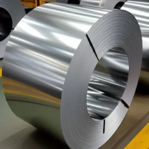
A traction motor is specified by speed first, and everything else follows from that one number. Silicon steel for EV motors therefore arrives as a chain, not a list. One speed sets the frequency, and that frequency then sets the gauge. Jiangsu Zhongtong Weiye Special Steel Co., Ltd. walks the chain below, using a non-oriented electrical steel sheet as the example.
The Short Answer
Most traction motors take 0.20 to 0.27 mm non-oriented strip, and the choice sits inside that band. A 4-pole machine at 15,000 rpm runs near 500 Hz, and an 8-pole machine reaches 1,000 Hz. Hence the gauge is a function of pole count and top speed, not of vehicle size.
Link One — Speed Sets Frequency
Electrical frequency follows pole count and speed, so one rule covers every design. A 4-pole motor at 15,000 rpm runs 500 Hz, while an 8-pole motor at the same speed runs 1,000 Hz. That doubling changes the loss split, before any material is chosen. Therefore, the pole count is the first decision, and it belongs to the machine designer, not to the steel buyer.

Link Two — Frequency Sets the Split
Eddy loss grows with frequency squared, so its share rises as speed climbs. At 50 Hz the hysteresis term usually leads, although at 500 Hz the eddy term can overtake it. That reversal means a sheet which wins at grid frequency loses at traction frequency, since the ranking flips. Hence the family rule from transformer work stops applying here. The loss note splits the terms.
Link Three — The Split Sets the Gauge
Once eddy leads, thickness becomes the strongest lever, because the term scales with gauge squared. A step from 0.27 to 0.20 mm leaves 55 percent of that component, since the ratio squares to 1.82. Hysteresis barely moves. A step from 0.27 to 0.25 mm cuts it 1.17 times only. The gain therefore shrinks fast near the top of the band. Therefore, a high-speed design pays for the thin stop, and a moderate one may not.
Link Four — The Gauge Sets the Strength
A rotor turns at speed, so the lamination must carry centrifugal load without yielding anywhere. Thin strip arrives with the same yield strength as thick strip, near 300 to 380 MPa after anneal. Chemistry does not change with gauge. The rotor bridges decide whether the shape survives, while the gauge decides only how many pieces run. Hence strength is a geometry question, and the gauge changes only labour.
The Carrier Adds Its Own Bill
An inverter switches near 8 to 10 kHz, and those harmonics deposit extra loss inside the core. The flux swing at each carrier cycle stays small, although the frequency is high. Published figures often put harmonic loss near 10 to 20 percent of the total, though the share moves with modulation. Hence a designer should test at the carrier frequency, not only at the fundamental.
What the Rotor Needs
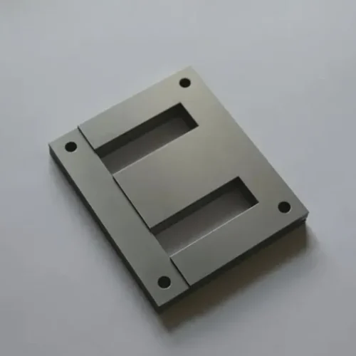
The rotor differs from the stator in duty, because it sees fewer flux reversals and more mechanical stress. A rotor lamination often keeps a thicker gauge for stiffness, while the stator takes the thin stop. The core type note sorts those duties. Annealing after stamping relieves stress and lowers loss, although it also lowers yield by a noticeable margin. Therefore, a rotor and a stator can carry two different gauges in one motor.
A 90 kW Ledger
A 90 kW motor at 95.2 percent efficiency burns about 4.54 kW. Iron loss takes roughly a quarter of that figure. That puts iron near 1.14 kW, and half of it may sit in the eddy term. A thin gauge attacks that half, while it leaves hysteresis alone. Hence the saving is real yet partial, and the model should say so. The advantages note lists those gains in order.
What Goes Wrong
One buyer keeps 0.35 mm for a 15,000 rpm stator, then pays in eddy loss. Another anneals a rotor lamination which needed its yield strength. A third tests only at 50 Hz, so the carrier harmonics go unseen. Those three errors arrive monthly.
What We Do Not Do
We do not melt or roll steel. We do not design the rotor, since the bridges belong to the customer’s engineer. Nor do we promise a loss figure at a carrier frequency the mill never tested.
Those limits keep the answer honest, and they keep a motor programme on schedule.
Specify Your Order
Give the pole count, the top speed, the gauge, and the anneal state, since four fields run the chain. Add the carrier frequency when the drive is inverter-fed. A silicon electrical steel sheet then ships with its loss basis printed. The thin gauge note covers the 0.20 mm stop. That reply usually takes a day.
Related Reading
Our range note places each gauge in a motor duty. The motor note explains why the oriented family fails here. A hub page answers six basic questions.
Frequently Asked Questions
0.20 to 0.27 mm, in non-oriented grades.
Because it doubles the frequency at one speed, and the eddy share follows.
No, since strength follows chemistry and anneal, and the gauge barely enters.
Only if the design can spare the yield, and most rotors cannot.
No, since the carrier adds its own loss on top of the fundamental.
- Email: vera.liang@ztwysteel.com
- Location: Xishan District, Wuxi, Jiangsu, China
- Supply range: CRGO and CRNGO 0.20–0.65 mm, four coating classes
- Slitting: 20–1,250 mm, ±0.05 mm, burr under 0.02 mm
- Documentation: MTC EN 10204 3.1 with grade, thickness and loss basis, 3.2 on request




 English