

35W300 Non-Oriented Silicon Steel: Properties and Frequency Loss
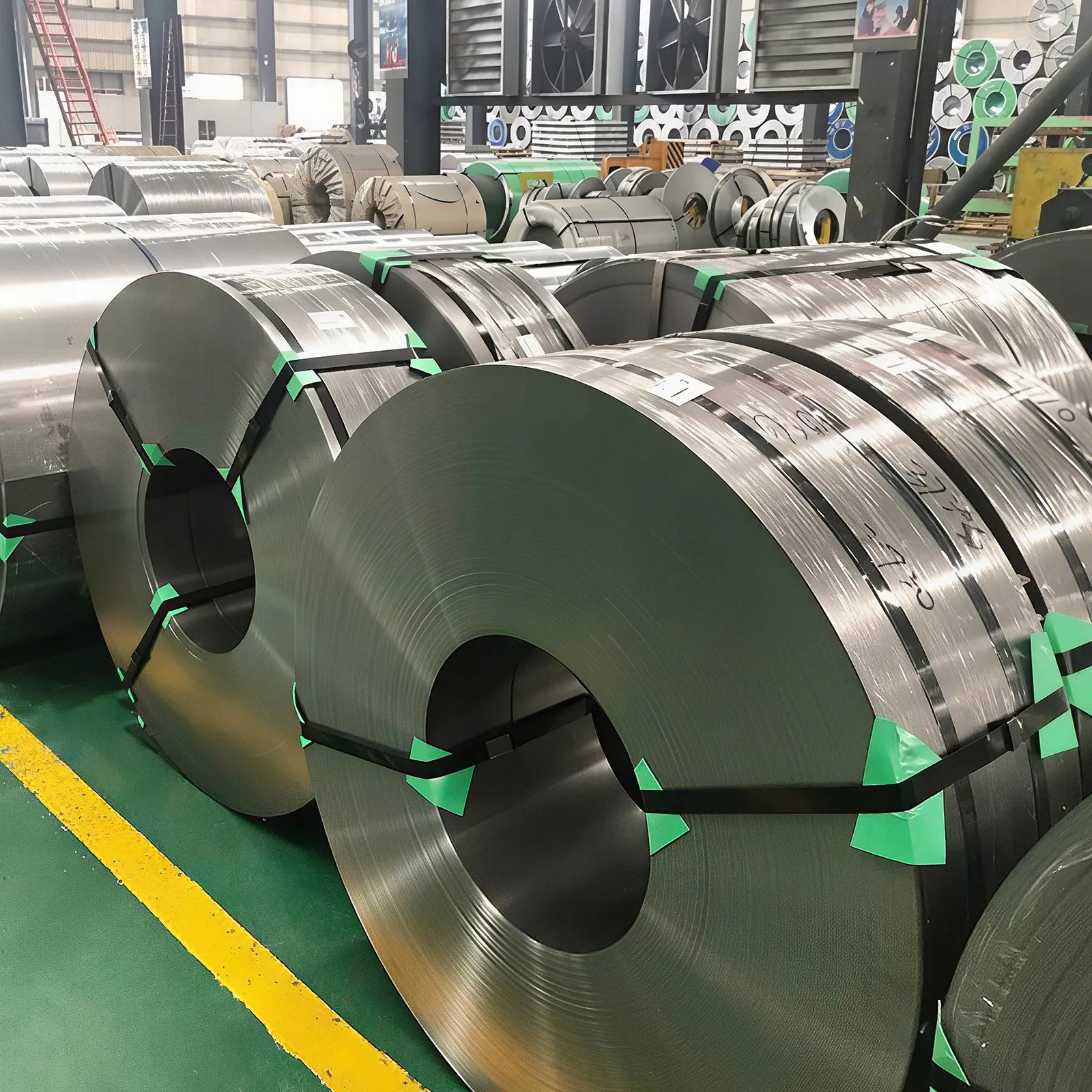
35W300 is a 0.35 mm non-oriented silicon steel with a guaranteed loss ceiling of 3.00 W/kg at 1.5 T, 50 Hz. It is a mid-to-high grade for the 0.35 mm thickness, above 35W440 in efficiency and below 35W250. What makes it interesting is not the 50 Hz figure alone but how the loss behaves when the machine runs faster than mains frequency, which is the case for inverter-driven and 400 Hz equipment. This page sets out the guaranteed values, derives the loss split from the standard figures, and explains what has to be measured rather than extrapolated. It sits within the wider non-oriented electrical steel range.
Guaranteed Values
The GB/T 2521.1 grade table sets these limits:
| Property | 35W300 |
| Nominal thickness | 0.35 mm |
| Conventional density | 7.65 kg/dm³ |
| P1.5/50, maximum | 3.00 W/kg |
| P1.5/60, maximum | 3.74 W/kg |
| J2500, reference | 1.49 T |
| J5000, minimum | 1.62 T |
| J10000, reference | 1.70 T |
| Loss anisotropy | ±17% |
| Minimum bend count | 3 |
| Minimum stacking factor | 0.95 |
| Tensile strength Rm, minimum | 420 MPa |
| Elongation A50mm, minimum | 11% |
Two entries are worth flagging before the frequency discussion. The anisotropy tolerance is ±17%, wider than the ±10% that applies to 0.50 mm grades, so transverse-path loss can run considerably above the with-rolling figure. And the minimum bend count is 3, against 10 on the 0.50 mm grades; the thinner, higher-silicon sheet takes fewer reverse bends before cracking, which shows up in handling and in the care needed during slitting and stacking. The M-series grade comparison places 35W300 against the American notation bands.
Reading Standard Grades Against the Density Ladder
Density tracks silicon content, and silicon sets both loss level and mechanical behaviour. In the 0.35 mm band the ladder runs from 7.60 kg/dm³ at the low-loss end to 7.70 kg/dm³ at 35W440; 35W300 sits at 7.65, so it carries real silicon rather than being a low-grade sheet with a better surface. Silicon raises resistivity, and resistivity governs eddy-current loss.
Deriving the Loss Split From Two Standard Figures
The standard guarantees only two loss figures, at 50 Hz and 60 Hz. That pair is enough to say something useful about where the loss comes from, because hysteresis loss rises with frequency and eddy-current loss rises with frequency squared.
For 35W300 the ratio of the two ceilings is 3.74/3.00 = 1.247. If all the loss were hysteresis the ratio would be 1.20; if all were eddy current it would be 1.44. Solving between those bounds puts the split at roughly 80% hysteresis and 20% eddy current at 1.5 T.
Running the same calculation across neighbouring grades gives a pattern worth knowing:
| Grade | Thickness | P60/P50 ratio | Eddy share at 50 Hz |
| 35W300 | 0.35 mm | 1.247 | about 19% |
| 50W470 | 0.50 mm | 1.255 | about 23% |
| 50W600 | 0.50 mm | 1.258 | about 24% |
| 35W440 | 0.35 mm | 1.273 | about 30% |
Two variables show up. Thickness lowers the eddy share, since eddy loss scales with the square of gauge. Silicon raises resistivity and also lowers the eddy share, which is why 35W440 carries a larger eddy fraction than 35W300 despite the same thickness: it has less silicon.
What Happens at 400 Hz
On the same split, scaling to 400 Hz multiplies hysteresis by 8 and eddy current by 64. For 35W300 that works out to a combined multiplier near 19, which on the 50 Hz ceiling implies a figure an order of magnitude higher than 3.00 W/kg.
That number is a scaling illustration, not a design value, for three reasons:
- Flux level changes.High-frequency designs rarely run at 1.5 T. A 400 Hz machine often works at 1.0 T or below, where both loss components are far smaller.
- The split is not constant.Domain structure, grain size and skin effect inside the sheet all shift at high frequency, so hysteresis and eddy do not keep their 50 Hz proportions.
- Measurement method changes.Above mains frequency the Epstein frame and single-sheet tester behave differently, and the mill’s measured curve is the only reliable source.
So the practical rule is: use the 50/60 pair to understand which mechanism dominates, then ask the mill for a measured curve at the actual frequency and flux. Mills that publish high-frequency data usually quote it at P1.0/400 (1.0 T, 400 Hz) rather than at 1.5 T, precisely because that is the working point real equipment uses.
Why Thickness Beats Grade at High Frequency
Because eddy loss scales with the square of gauge, halving thickness cuts that component by roughly four times, while dropping a grade step moves the total by a much smaller margin. At 400 Hz the eddy share is no longer the minority term, so a thin sheet of a mid grade often beats a thick sheet of a premium grade. That is the logic behind specifying 0.20 mm or 0.27 mm material for high-speed rotors and 400 Hz transformers instead of pushing the 0.35 mm band to its lowest-loss grade. Choosing a grade by operating frequency sets out that selection logic across the frequency range, and 0.35 against 0.50 mm covers the thickness decision at mains frequency.
Where 35W300 Fits
The grade suits small and medium induction motors with a real efficiency target, high-speed and inverter-fed machines where the carrier frequency pushes loss up, 400 Hz ground power and aerospace equipment, and compressor or pump motors running continuously. It is a reasonable default when the design needs better than 35W440 but cannot justify the cost of 35W250 or a thinner gauge.
It is over-specified for intermittent-duty small motors that a 50W600 or 50W800 grade would serve at lower cost, and under-specified for high-frequency work that needs thinner material rather than lower-loss 0.35 mm sheet.
FAQ
Is 35W300 better than 50W470? Not directly comparable. 35W300 is 0.35 mm and 50W470 is 0.50 mm, so the thinner sheet wins on eddy current while the thicker sheet carries more total active steel per stack height. The comparison has to be made on the finished core.
What is the loss at 400 Hz? Not published in the standard, which guarantees only 50 Hz and 60 Hz. Ask the mill for a measured curve at the actual frequency and flux; high-frequency data is usually quoted at 1.0 T, 400 Hz.
Why is the anisotropy tolerance so wide? ±17% is the standard allowance for this thickness band. The thinner, higher-silicon sheet loses more when flux runs across the rolling direction, so a core with mixed flux paths should be sized on the transverse figure.
Does the low bend count matter in production? Yes. Three reverse bends against 10 on 0.50 mm grades means less tolerance for handling abuse, so slitting, stacking and forming need care to avoid edge cracking.
Can 35W300 be used at 50 Hz in a standard motor? Yes, and it is a sensible choice for efficiency-targeted 50 Hz machines. The high-frequency discussion here is about inverter and 400 Hz duty, not a limitation of the grade.
Sizing 35W300 for an inverter-fed or 400 Hz design? Send the switching frequency, working flux and stack height to vera.liang@ztwysteel.com, and we will confirm the grade and request the measured high-frequency curve for the lot. The silicon electrical steel sheet range lists the stocked gauges, and selecting non-oriented steel for motors covers selection above the grade level.




 English