

Silicon Steel Grade Selection by Operating Frequency
Choosing silicon steel comes down to three decisions: whether the flux runs one way or rotates, how thick the strip should be, and which loss grade the budget allows. The second decision is set almost entirely by the operating frequency, and it is the one buyers get wrong most often. This note maps each frequency band to a typical thickness range, separates that choice from the grain-orientation decision, and lists what thin gauge costs in return. The silicon steel range is organised around the same three decisions, so the selection here follows the material itself.
Frequency Sets Thickness, Not Type
A common first question is which grade runs at high frequency. The two decisions should be separated before any grade number is read.
Grain orientation is decided by the flux path, not the frequency. If the core carries flux in one steady direction, grain-oriented silicon steel is the default, whatever the frequency. If the flux rotates through the lamination plane, as it does in every rotating machine, non-oriented silicon steel is the default, again whatever the frequency.
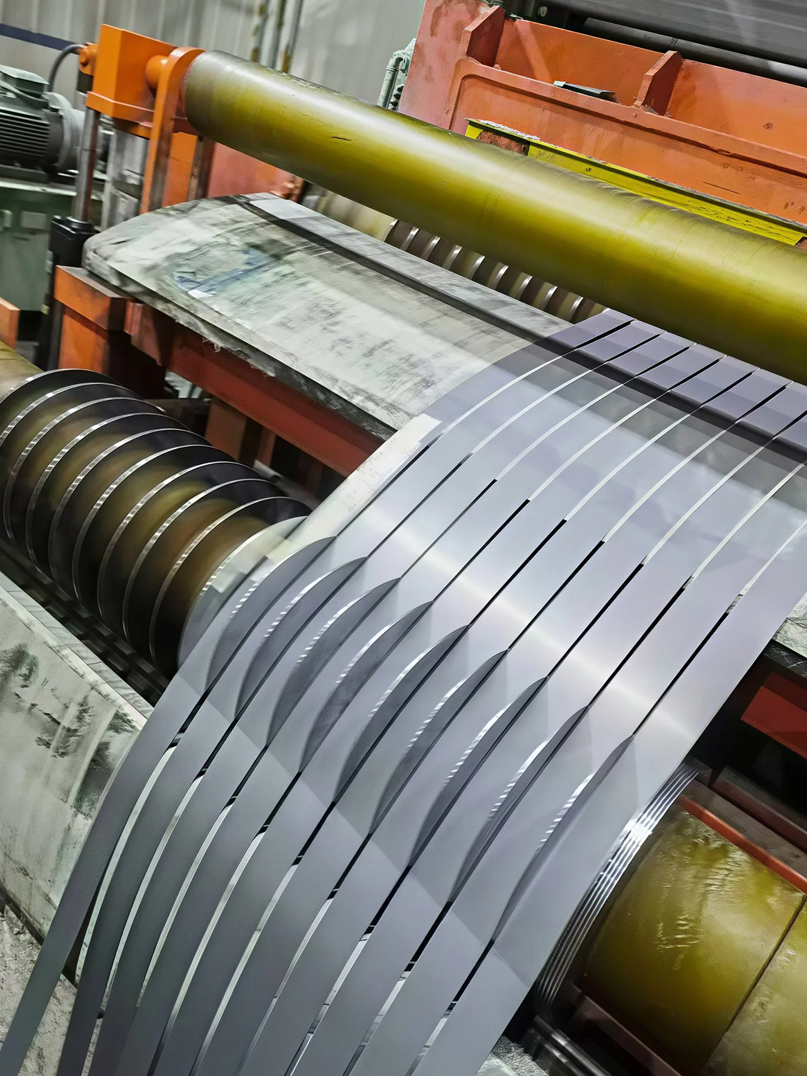
Frequency decides the thickness. As frequency climbs, eddy-current loss takes over from hysteresis loss, and the only way to hold that part down is to roll the strip thinner. The grade number then picks how much loss remains once the gauge is set.
The Frequency–Thickness Matrix
The bands below are typical engineering ranges, not hard cut-offs. The final choice still has to be checked against the loss curve at the design flux density.
| Operating frequency | Typical oriented thickness | Typical non-oriented thickness | Common equipment |
| 50–60 Hz | 0.30, 0.27, 0.23 mm | 0.50, 0.35 mm | Distribution and power transformers, industrial motors, generators |
| 200–400 Hz | 0.23, 0.20 mm | 0.35, 0.27, 0.20 mm | Servo motors, EV traction motors, aircraft-frequency supplies, medium-frequency transformers |
| 400 Hz–2 kHz | 0.20, 0.18, 0.15 mm | 0.20, 0.15 mm | High-speed motors, traction auxiliaries, high-frequency reactors |
| Above about 2 kHz | Thin oriented grades in special cases | Ultra-thin non-oriented, or another soft-magnetic material | High-frequency power supplies; amorphous or ferrite usually takes over here |
For a 50 Hz distribution transformer, 0.30 or 0.27 mm oriented strip is the usual balance between loss, stacking and price. For a 60 Hz design the eddy-current part rises by roughly 44% compared with 50 Hz at the same gauge, which pushes the choice toward 0.27 or 0.23 mm. The three-thickness transformer steel comparison walks through that trade in detail.
Why Thickness Follows Frequency
Classical eddy-current loss scales with the square of thickness and the square of frequency. Holding flux density fixed, halving the gauge cuts the eddy-current part to roughly one quarter. That is why thin gauge earns its keep as frequency rises: at 50 Hz the eddy part is small, and going thinner buys little; above a few hundred hertz it dominates, and the thicker gauges burn through energy rather than cut material.
One qualification matters. The square rule applies to the eddy-current part only. Hysteresis loss does not fall with thickness, so total core loss drops by less than the eddy number suggests. A 0.35 mm to 0.20 mm move removes about two thirds of the eddy contribution, not two thirds of the total loss. Core loss as the critical transformer indicator covers how those two parts add together on the mill certificate.
What the Grade Number Means in Each Band
Once thickness is set, the grade number states the maximum specific loss at a stated test point. The examples below are typical, and every design should be checked against the supplier’s loss curve at its own induction and frequency.
| Band | Non-oriented example | Thickness | Typical loss figure | Fit |
| 50–60 Hz general | 50W470 / M470-50A | 0.50 mm | 4.70 W/kg at 1.5 T, 50 Hz | General-purpose motors, pumps, fans |
| 50–60 Hz efficient | 35W300 | 0.35 mm | 3.00 W/kg at 1.5 T, 50 Hz | High-efficiency industrial motors |
| Servo and traction | 35W250 | 0.35 mm | 2.50 W/kg at 1.5 T, 50 Hz | Premium-efficiency and servo machines |
| Oriented, 50/60 Hz | B27G120 class | 0.27 mm | About 1.20 W/kg at 1.7 T, 50 Hz | Efficient distribution transformers |
The loss figure on a grade name is quoted at one test point. It does not transfer unchanged to 400 Hz, where total loss rises sharply. A 400 Hz selection needs the supplier’s curve at that frequency, not the 50 Hz number on the general catalogue page.
Electrical Frequency Is Not Shaft Speed
When the equipment is a motor, the frequency the steel sees is electrical frequency, not the revolutions per minute printed on the nameplate. Electrical frequency equals the number of pole pairs multiplied by speed in revolutions per second. A 14-pole drone motor turning at 6,000 rpm is already running near 700 Hz even though the rpm looks ordinary.
This is where high-speed and traction designs surprise buyers who sized the gauge off shaft speed alone. The EV motor non-oriented steel guide covers the traction end of that calculation; the check before specifying any gauge is to convert rpm and pole count into hertz first.
The Cost of Going Thin
Thinner strip is not free, and it should not be specified where the loss budget does not require it. Three costs follow every gauge reduction:
- Stacking factor drops.A 0.35 mm stack packs roughly 0.97 steel fraction; a 0.10 mm stack can sit near 0.88–0.92, so more stack height is needed for the same magnetic section.
- Stamping slows.Thin, high-silicon strip needs tighter die clearance and produces more burr risk; the same line turns out fewer laminations per hour than it does on 0.35 mm.
- Unit price rises.Thin gauge carries a premium per kilogram, and waste from stamping narrow parts adds to it.
The practical rule is to use the thinnest gauge the loss budget actually requires, and stop there. Under about 200 Hz, 0.35 or 0.50 mm is easier to buy, cut and stack; above about 400 Hz, 0.20 mm or thinner becomes the safer call.
FAQ
Does high frequency mean grain-oriented steel? No. Orientation follows the flux path. A high-frequency motor still rotates, so it takes non-oriented steel; a high-frequency transformer core still carries one-way flux, so it takes oriented steel.
Can I use a thick grade at 400 Hz to save cost? The material cost may be lower, but the eddy-current loss will be high enough that the running temperature and efficiency rarely justify it. Check the loss curve before accepting the quote.
What happens above a few kilohertz? Silicon steel loses its advantage there. Designs usually move to amorphous alloy or ferrite cores, which hold loss better at very high frequency.
Is 60 Hz always thinner than 50 Hz? Not automatically. The 60 Hz loss uplift pushes designs toward thinner gauge, but the thickness still follows the efficiency class and the available stack height, not the frequency alone.
Unsure which band your equipment falls into? Send the rpm, pole count and intended flux density to vera.liang@ztwysteel.com, and we will map it to a gauge and grade range before the order is specified.



 English