
What are EI silicon steel sheets used for?
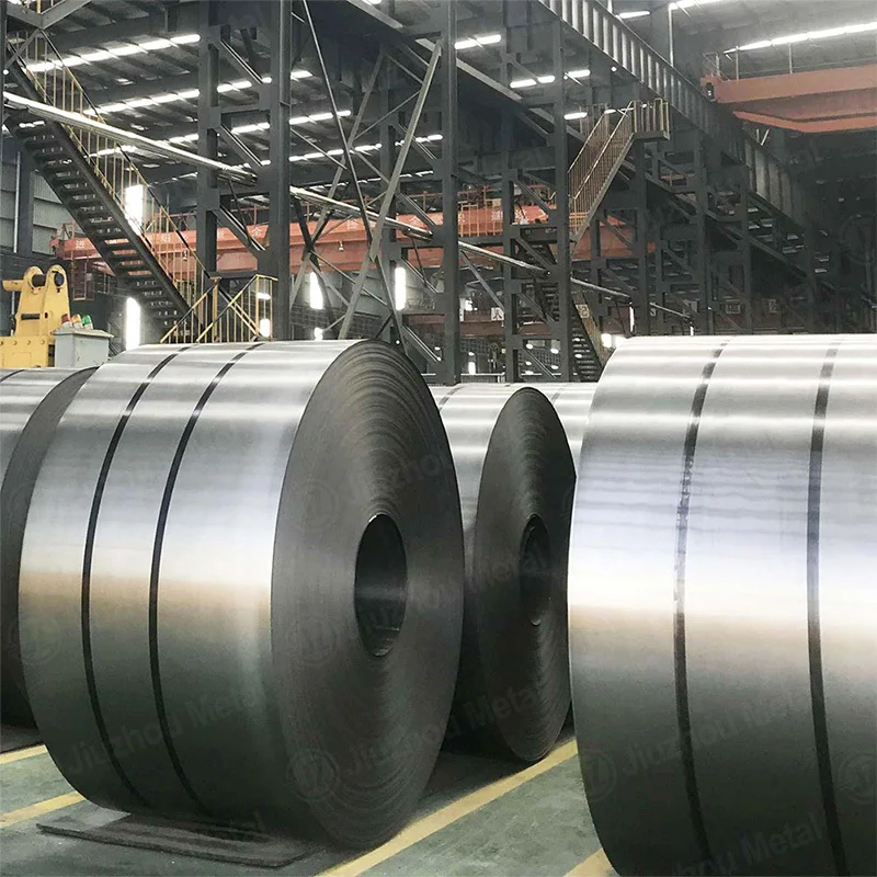
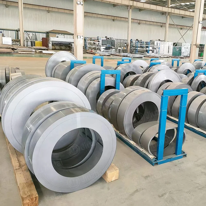
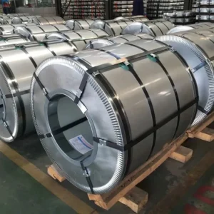
EI silicon steel sheets serve small and medium electromagnetic devices, and they stop serving large ones. In practice, an E-shaped stamping plus an I-shaped bar builds a closed core with one cheap die set. Consequently, EI laminations dominate control transformers, chokes, and servo cores. Jiangsu Zhongtong Weiye Special Steel Co., Ltd. supplies the coil those stampers cut. Below, therefore, is a use map arranged by power rating.
Rung 1 — 30 VA to 500 VA
Instrument transformers, PCB-mounted transformers, and doorbell or thermostat supplies sit here. EI-48 to EI-75 sizes dominate, since tongue widths stay small. Moreover, 0.35 mm non-oriented sheet keeps stack height compact. Because volumes are large, stampers accept die cost happily.
Rung 2 — 500 VA to 5 kVA
Isolation transformers, medical auxiliary supplies, and audio output transformers occupy this band. Stacking usually interleaves E and I, so joint reluctance drops. Hence flux distribution improves without extra cost. In addition, 0.50 mm sheet often suffices, because frequency stays at 50 or 60 Hz.
Rung 3 — 5 kVA to 100 kVA
Control and distribution transformers, chokes for drives, and reactor cores fill this rung. EI-114 through EI-300 sizes appear, and gauge falls back to 0.35 mm for loss control. Furthermore, customers often request annealed cores after stamping, since punching stress raises loss.
Rung 4 — Above 100 kVA
Here EI loses, and the reason is geometric. Butt joints at the corners create reluctance, so no-load current rises sharply as cores grow. Consequently, utility transformers use mitered or step-lap wound cores instead. Claims that EI laminations serve substation transformers therefore mislead buyers.
Why the Ladder Ends Where It Does
A core’s joint loss scales with the number of joints per unit of flux path. Small cores tolerate that penalty, whereas large cores cannot. Moreover, mitered cores cut loss by 10–15% at equal weight, so the crossover arrives near 50–100 kVA. Beyond that, the die savings no longer justify the electrical penalty.
Gauge and Grade by Rung
- Rung 1: 0.35 mm, M36 or M47, since cost dominates.
- Rung 2: 0.50 mm, M36, since frequency is low.
- Rung 3: 0.35 mm, M19, since loss starts to matter.
- Rung 4: not EI, so specify oriented grades instead.
For motor work at similar ratings, M19 Non Oriented Electrical Steel remains the default choice. Cheaper frames generally take M36 Non Oriented Electrical Steel.
Where EI Still Beats Alternatives
Tooling cost separates the two routes, because one EI die serves an entire size family. Consequently, small batches and custom ratios favour EI, while volume programs migrate to wound cores. In addition, EI handles odd aspect ratios, since E and I interlock in many stack heights.
Repair shops also prefer EI, because a damaged lamination can be replaced singly. Wound cores, by contrast, cannot be repaired that way.
Grade background sits in our silicon steel grades overview. Machine-level context appears in the silicon steel applications guide.
Coating and Insulation Practicalities
Inter-laminar insulation prevents short circuits, and damaged coating causes local heating. Therefore, specify coating type with the stamping house, since some varnishes attack certain films. Moreover, burr height must stay below 0.03 mm, because burr bridges insulation at the edges.
Stacking factor typically reaches 0.94–0.96, so build height follows gauge plus coating. Hence gauge tolerance of ±0.02 mm protects the window height your designer calculated.
Frequently Asked Questions
No, since mitered or step-lap cores replace them above roughly 100 kVA.
0.35 mm and 0.50 mm, with 0.35 mm preferred where loss matters.
0.35 mm and 0.50 mm, with 0.35 mm preferred where loss matters.
Yes, and stress-relief annealing usually restores 5–10% of lost loss performance.
To spread the joint, which lowers reluctance and mechanical hum.
What We Do Not Do
- We do not stamp E and I shapes.
- We do not stack or anneal finished cores.
- We do not hold EI dies for customers.
Consequently, we supply slit coil and documentation, while your stamper owns tooling.
Specify Your Order
- State the core size and stack height.
- Name the grade, or give the loss limit at 1.5 T.
- Give slit width and coil weight, then confirm tonnage and port.
We reply with stock, price, and test data within one working day.
- Email: vera.liang@ztwysteel.com
- Location: Xishan District, Wuxi, Jiangsu, China
- Supply range: CRNGO M19–M47 at 0.35–0.65 mm, CRGO M4/M5 at 0.23–0.35 mm
- Slitting tolerance: ±0.05 mm, burr under 0.02 mm
- Documentation: MTC EN 10204 3.1, core loss per ASTM A343 / IEC 60404-2, coating specification



 English