
High Saturation Flux Silicon Steel: Enhancing Performance in High-Power Motor Manufacturing
High saturation flux silicon steel promises more torque from a smaller frame, yet the promise contains a trade worth understanding. In practice, saturation induction comes mostly from iron, while silicon lowers it slightly in exchange for lower loss. Consequently, a “high-Bs” grade is a balancing act rather than a pure upgrade. Jiangsu Zhongtong Weiye Special Steel Co., Ltd. supplies both branches of that trade. Below, therefore, are the five conflicts every motor designer must settle.
Conflict 1 — Induction Against Silicon Content
Pure iron saturates near 2.1 T, and 3% silicon drops that to about 2.0 T. Raising silicon to 4.5% costs another 0.05 T, while a 6.5% Fe-Si alloy falls nearer 1.85 T. Hence silicon buys resistivity and loss reduction by spending induction.
For traction motors, that trade usually stops at 3–3.5% silicon, because torque density matters more than the last watt of loss.
Conflict 2 — Thin Gauge Against Stacking Factor
Thinner sheet cuts eddy loss, since that term scales with thickness squared. However, each lamination adds a coating interface, so stacking factor falls from about 0.96 at 0.50 mm toward 0.94 at 0.20 mm. Therefore, a thinner core sometimes needs a longer stack for equal flux.
Cost rises at the same time, because rolling thin gauge lowers yield. Subsequently, 0.27 mm rarely pays back below 400 Hz duty.
Conflict 3 — High Induction Operation Against Loss
Running a core at 1.7 T shrinks its cross-section, which saves copper and iron weight. Nevertheless, loss climbs steeply near the knee, so a 10% induction increase can add 20–30% to iron loss. Consequently, designers pick operating points from measured B-H data, not from catalogue Bs.
High-power motors typically sit between 1.5 T and 1.7 T, and the exact figure follows the cooling budget.
Conflict 4 — Low Loss Against Punchability
Silicon raises hardness and brittleness, so high-Si grades punch poorly and wear dies faster. Moreover, edge cracking appears when clearance is tight. Hence stampers often prefer 3% silicon plus annealing over exotic 6.5% alloys.
Where 6.5% sheet is used, special rolling and careful slitting become mandatory, and scrap rates rise accordingly.
Conflict 5 — Efficiency Class Against Material Cost
IE4 designs need low loss, and premium grades deliver it at a price premium of roughly 15–25%. However, the payback depends on duty hours, so a continuously running industrial drive recovers that premium quickly. By contrast, an intermittently used machine may never recover it.
Therefore, lifecycle arithmetic should precede grade selection, not follow it.
How This Lands in a Real Specification
- Fix the torque and speed envelope first, since that sets flux demand.
- Choose silicon content, usually 3–3.5%, then confirm B8 from test data.
- Set gauge from the fundamental frequency, not from habit.
- Specify stacking factor explicitly, because gauge and coating both affect it.
- Require core loss at the actual operating induction.
Those five decisions resolve the conflicts in order, and skipping any one shifts risk downstream.
Grade Options That Fit High-Power Frames
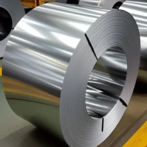
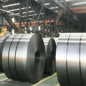
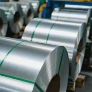
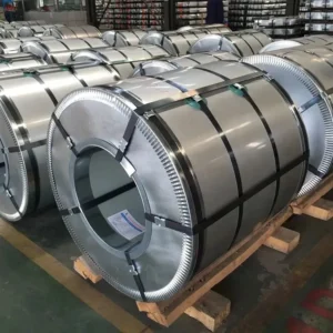
Mainstream stators usually specify M19 Non Oriented Electrical Steel at 0.47–0.50 mm. Larger, cost-sensitive frames take M36 Non Oriented Electrical Steel, where a modest loss penalty is acceptable.
Induction data is best read from measured curves, and our saturation magnetisation note explains the upper limit. Flux density definitions, meanwhile, appear in the B and H measurement guide.
Frequently Asked Questions
No, since it slightly lowers Bs while raising resistivity.
Around 1.88–1.92 T for grain-oriented grades, and 1.80–1.86 T for non-oriented.
Rarely, because brittleness raises stamping cost sharply.
0.20–0.27 mm, since eddy loss dominates there.
Not always, because loss and cooling limits cap the gain.
What We Do Not Do
- We do not design motors or cores.
- We do not stamp laminations.
- We do not guarantee efficiency class outcomes.
Consequently, we supply coil plus measured magnetic data, and your design team sets the operating point.
Specify Your Order
- State the torque, speed, and cooling arrangement.
- Name the grade, or give loss and B8 limits.
- Give gauge and slit width, then confirm tonnage and port.
We reply with stock, price, and magnetic data within one working day.
- Email: vera.liang@ztwysteel.com
- Location: Xishan District, Wuxi, Jiangsu, China
- Supply range: CRNGO M19–M47 at 0.35–0.65 mm, CRGO M4/M5 at 0.23–0.35 mm
- Slitting tolerance: ±0.05 mm, burr under 0.02 mm
- Documentation: MTC EN 10204 3.1, core loss and B8 per ASTM A343 / IEC 60404-2



 English