

Mastering Precision: Implementing Strict Thickness Tolerance Control in Silicon Steel Mass Production
Silicon steel thickness tolerance decides more than one line on a certificate, since it sets stacking factor, air gap, and core loss together. In practice, a 0.30 mm coil must hold ±0.02 mm across an entire batch. Jiangsu Zhongtong Weiye Special Steel Co., Ltd. slits that coil in Wuxi, so gauge consistency is our daily constraint. Below, therefore, are the five sources of drift and the way each one is held.
Why 0.02 mm Carries So Much Weight
Eddy loss rises with the square of sheet thickness, and consequently a 10% gauge overrun adds roughly 20% to eddy loss. Stacking factor falls at the same time, because ten thousand laminations amplify every deviation. Air gap control in motors suffers too, since slot fill varies with gauge. For transformer cores, extra thickness forces a rebuild of the window height. Hence gauge tolerance behaves as an efficiency parameter rather than a cosmetic one.
The Five Sources of Drift
Source 1 — roll thermal crown. Mill rolls grow with heat, so gauge wanders mid-campaign. Compensation therefore needs crown profiling plus closed-loop automatic gauge control.
Source 2 — control loop lag. The loop reacts after exit gauge has already moved. Consequently, dead time must stay under one roll revolution.
Source 3 — coating build. Insulation film adds 1–3 µm, which shifts the measured figure. Hence specify gauge before or after coating, and never leave the basis ambiguous.
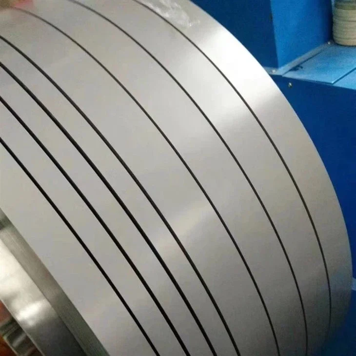
Source 4 — slitting tension. Poor tension creates burr and local thickening. Subsequently, slit coils need tension control and burr limits under 0.02 mm.
Source 5 — measurement drift. Contact and X-ray gauges disagree, especially when strip temperature varies. In addition, calibration intervals decide how much you truly know.
A Tolerance Budget That Adds Up
Budgeting beats blaming, because a ±0.02 mm band is consumed by four contributors:
- Mill gauge control: ±0.012 mm.
- Coating variation: ±0.004 mm.
- Measurement uncertainty: ±0.003 mm.
- Handling and edge effects: ±0.001 mm.
Summed arithmetically, those reach ±0.020 mm. In practice, statistical combination leaves margin, so root-sum-square arrives near ±0.013 mm. Therefore, the band holds comfortably when each contributor stays inside its own limit.
Why Mass Production Differs From One Coil
A single coil proves capability, whereas a 100-ton campaign tests stability. Campaign length exposes thermal drift, because roll temperature climbs coil after coil. It also reveals control-loop ageing, since hydraulics respond differently by the end of a run. Moreover, shift changes introduce human variance in sampling and handling.
Consequently, mills that hold tolerance over ten thousand tons usually publish a control plan, not just a certificate. Buyers should ask for it, and then compare it against incoming inspection results.
What Belongs in Your Specification
- State nominal gauge and tolerance on a defined basis.
- Name the test method, since ASTM A876 and GB/T 2521 define bands differently.
- Specify coating type, because C-5 and C-6 films build differently.
- Require gauge records per coil rather than per shipment.
- Fix slit width tolerance separately, as ±0.05 mm normally suffices.
Without those five lines, disputes arrive with the truck, and rework costs more than the coil. Furthermore, arbitration rarely favours either party.
What We Control and What We Do Not
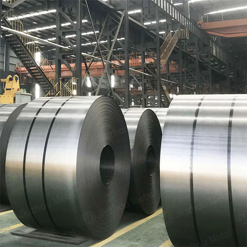
We slit and inspect coil; we do not roll or anneal it. Therefore, gauge at our dock reflects mill control plus our own handling. Sampling follows a fixed plan, since one check cannot represent a hundred tons. In addition, every coil ships with MTC EN 10204 3.1 and coil-level gauge records.
For standard motor grades, M19 Non Oriented Electrical Steel holds 0.47–0.50 mm within tight bands. Heavier frames take M36 Non Oriented Electrical Steel. Transformer cores usually specify M4 Grain Oriented Electrical Steel, where gauge errors show up as build height rather than loss.
Gauge discipline also cuts downstream scrap; our custom-size coil note explains how slit tolerance interacts with punching. Separately, our transformer efficiency explainer connects gauge to no-load loss.
Frequently Asked Questions
Yes, and premium mills hold ±0.015 mm routinely across a campaign.
It does, so the measurement basis must be stated in the purchase order.
Thermal crown and loop lag explain most of it, whereas handling explains very little.
Not the sheet itself, although burr and tension affect the effective build.
ASTM A876 and GB/T 2521, depending on origin and contract terms.
What We Do Not Do
- We do not operate a rolling mill.
- We do not anneal or coat strip.
- We do not certify core loss against your design.
Consequently, we supply slit coil with traceable gauge data and honest limits.
Specify Your Order
- State nominal gauge and tolerance.
- Name the coating type and measurement basis.
- Give slit width, then confirm tonnage and port.
We reply with stock, price, and gauge records within one working day.
- Email: vera.liang@ztwysteel.com
- Location: Xishan District, Wuxi, Jiangsu, China
- Supply range: CRGO M4/M5 at 0.23–0.35 mm, CRNGO M19–M47 at 0.35–0.65 mm
- Slitting tolerance: ±0.05 mm, burr under 0.02 mm
- Documentation: MTC EN 10204 3.1, coil-level gauge records, core loss per ASTM A343 / IEC 60404-2






 English