

What is stacking factor of silicon steel laminations?
What Is the Stacking Factor of الفولاذ السيليكوني Laminations?
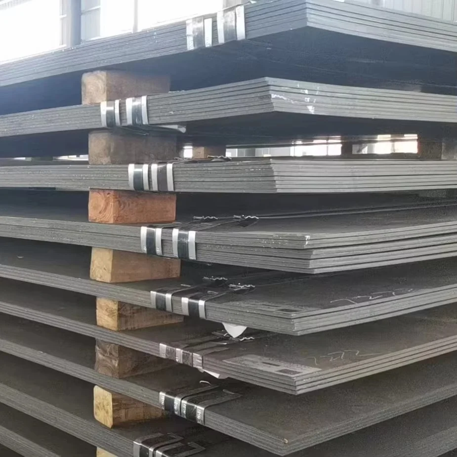
For design engineers and procurement specialists in transformer and motor manufacturing, material efficiency directly impacts performance and cost. One critical metric often overlooked is the stacking factor of فولاذ السيليكون laminations. This value determines how much active magnetic material fits into a given core volume. It also influences core losses, weight, and overall equipment dimensions. Understanding this parameter helps optimize designs for power transformers, industrial motors, and servo systems. This article explains the stacking factor in clear terms. It also covers measurement methods, typical values, and practical implications for your supply chain.
Defining the Stacking Factor
The stacking factor is the ratio of the net steel volume to the gross core volume. In other words, it represents the actual percentage of magnetic material present after assembly. Manufacturers calculate it as the total thickness of all laminations divided by the core stack height. For example, a factor of 0.95 means that 95% of the stack is steel, while 5% consists of coatings and air gaps. This factor never reaches 1.0 because each lamination carries an insulating layer. These layers prevent eddy currents but also reduce the effective cross-sectional area. Therefore, the stacking factor of فولاذ السيليكون laminations directly affects flux density and ampere-turns requirements.
Why This Metric Matters for Core Design
A higher stacking factor allows a smaller core for the same magnetic performance. This reduces copper wire length and resistive losses. It also lowers overall weight and material costs. Conversely, a lower factor forces designers to increase core size or use more turns. That raises expenses and expands equipment footprints. For large power transformers, even a 1% change in stacking factor can shift total cost by thousands of dollars. For servo motors, it affects torque density and response time. Thus, specifying the correct stacking factor of silicon steel laminations is a fundamental decision in electromagnetic device engineering.
Factors That Influence the Stacking Factor
Several variables affect the final stacking factor in production. The thickness of the insulation coating is the primary factor. Organic or inorganic coatings add thickness without contributing to magnetic flux. Surface roughness and flatness of the steel strip also play a role. Wavy edges or uneven surfaces create micro-gaps between layers. Burrs from cutting or punching operations increase inter-laminar spacing. Moreover, the clamping pressure during core assembly compresses the stack. Higher pressure reduces air gaps and improves the factor. However, excessive pressure may damage the coating. Therefore, manufacturers balance these factors to achieve an optimal value.
Typical Values for Industrial Applications
Most commercial silicon steel laminations have stacking factors between 0.92 and 0.98. Non-oriented grades commonly range from 0.95 to 0.97. Grain-oriented steels, used in power transformers, often reach 0.96 to 0.98. Thinner laminations, such as 0.27 mm or 0.23 mm, tend to have lower factors due to higher coating ratios. Thicker materials, like 0.50 mm, can achieve factors above 0.97. However, thinner grades reduce eddy current losses at high frequencies. Thus, the choice involves trade-offs between stacking factor and core loss. For high-efficiency designs, engineers may accept a slightly lower factor to gain better loss performance.
How to Measure the Stacking Factor Accurately
Quality control departments typically measure this parameter using a simple method. They cut a sample stack of laminations with a known number of sheets. Then they measure the total height under a standard clamping pressure. They also measure the nominal thickness of each sheet from the mill certificate. Multiplying the nominal thickness by the sheet count gives the theoretical height. The actual measured height divided by the theoretical height yields the stacking factor. For greater precision, they use a micrometer with a flat anvil. Some labs employ automated systems that apply consistent pressure and record data digitally. This measurement should be performed on every batch to ensure consistency.
Impact on Core Loss and Excitation Current
The stacking factor directly influences the core’s effective cross-sectional area. A lower factor reduces the area, which increases the flux density for a given voltage. Higher flux density leads to higher specific core loss (W/kg). It also raises the magnetizing current needed to drive the flux. Both effects degrade efficiency and increase operating temperature. For transformer manufacturers, this means higher no-load losses and potential compliance issues. For motor makers, it means reduced power factor and higher copper losses. Therefore, controlling the stacking factor of silicon steel laminations is essential for meeting energy efficiency standards like IE4 or NEMA Premium.
Considerations for Procurement and Supply Chain
When sourcing laminations, buyers should specify a minimum stacking factor. They should also request test reports from each production lot. Variation between suppliers can be significant due to different coating chemistries and rolling processes. Some suppliers offer higher factors by using thinner coatings or better surface finishing. However, these improvements may raise the unit price. Procurement managers must evaluate the total cost of ownership. A slightly higher factor may justify a higher material cost if it reduces overall core size and copper usage. Additionally, consistent stacking factor reduces manufacturing variances, which improves yield and reduces rework.
Best Practices for Design Engineers
Design software often assumes an ideal stacking factor, such as 0.97. But actual production values may differ. Therefore, engineers should add a safety margin in their magnetic circuit calculations. They can also request prototype stacks to verify the factor under their specific clamping conditions. Using a conservative estimate helps avoid performance shortfalls. Furthermore, they should communicate clearly with lamination suppliers about the required factor. Regular audits of incoming materials ensure that the supplier maintains quality. For custom core geometries, the stacking factor may vary across the stack due to tooling wear. Periodic tool maintenance minimizes this variation.
Practical Example of Stacking Factor Effect
Consider a 1000 kVA transformer designed with a stacking factor of 0.96. If the actual factor drops to 0.94, the core area reduces by about 2%. To maintain the same voltage, the flux density increases by 2%. This raises core loss by roughly 4% to 5%, depending on the material. For a transformer operating 24/7, that extra loss translates to significant annual energy cost. It also increases the core temperature, shortening insulation life. Thus, a small deviation in the stacking factor of silicon steel laminations has substantial economic and reliability consequences.
Future Trends in Lamination Technology
New coating materials aim to reduce thickness while maintaining insulation properties. Some advanced grades use laser-scribed surfaces to minimize air entrapment. Improved rolling techniques produce flatter strips with tighter thickness tolerances. These innovations may push typical stacking factors toward 0.98 or even 0.99. However, they also require higher precision in stamping and annealing. For high-frequency applications, such as electric vehicle motors, thinner laminations are essential. Their lower stacking factors may be acceptable because the reduced eddy losses outweigh the area penalty. Design engineers must stay informed about these developments to make optimal choices.
Conclusion: A Critical Parameter for Core Efficiency
The stacking factor of silicon steel laminations is not a minor specification. It affects core size, material cost, losses, and thermal performance. For transformer and motor manufacturers, controlling this factor ensures predictable electromagnetic behavior. Procurement teams should treat it as a key quality indicator. Design engineers must account for its variability in their simulations. By understanding its measurement, typical ranges, and influencing factors, you can make better technical and commercial decisions. Ultimately, a well-managed stacking factor contributes to more competitive, reliable, and efficient electrical equipment. Keep this metric on your checklist for every core material evaluation.







 English
  Japanese
  Korean
  French
  German
  Spanish
  Portuguese
  Russian
  Arabic
  Italian
  Turkish
  Dutch
Dutch  Polish
  Swedish
  Danish
  Norwegian
  Finnish
  Greek
Greek  Hungarian
  Czech
Czech  Romanian
  Bulgarian
  Slovenian
  Croatian
  Slovak
  Malay
Malay  Indonesian
  Thai
Thai  Vietnamese
  Myanmar
  Khmer
Khmer  Lao
Lao  Tagalog
  Hindi
Hindi  Bengali
  Urdu
Urdu  Nepali
  Sinhala
  Hebrew
  Ukrainian
  Serbian
  Icelandic
  Swahili