
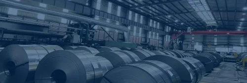
How to Test the Tensile Breaking Force of Stacked Silicon Steel Laminations
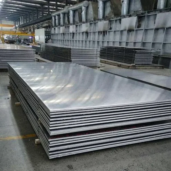
Tensile testing of stacked 실리콘강 laminations is carried out with a universal tensile testing machine matched with dedicated fixtures. Three core links — equipment selection, specimen preparation and standardized operation — directly determine the accuracy of test results.
I. Selection of Appropriate Test Equipment and Fixtures
The measuring range of the tensile tester shall cover the expected tensile strength of 실리콘강; it is common to select equipment with a range about 20% higher than the estimated maximum load. A precision class of no less than Class 0.5 is recommended to capture subtle variations during the material yielding stage. A test speed of 1–5 mm/min is ideal; excessive speed will distort test data. Digital readout or automatic data logging functions are preferred. Manual reading of analog pointer gauges tends to introduce human errors.
Fixture selection depends on the shape and thickness of 실리콘강 laminations. Flat jaw fixtures work for standard rectangular stacked pieces, while custom fixtures may be required for special-shaped or holed laminations. The core requirement is full contact between clamping surfaces and specimens to avoid premature fracture caused by localized stress concentration.
Jaw texture design is critical: overly sharp serrations damage specimen edges, while excessively smooth surfaces lead to slipping. Cross serrations with moderate surface roughness are widely applicable.
II. Specimen Preparation and Test Procedures
Use professional shearing tools to ensure smooth specimen edges during preparation, and remove all burrs with fine sandpaper. Sampling areas shall be at least 20 mm away from the material edges, where grain orientation may be non-uniform. Measure thickness at a minimum of three points and adopt the average value; record actual dimensions for strength calculation.
If specified by test standards, machine specimens into designated geometries with dedicated sampling tools. Without special requirements, testing laminations in their original as-stacked state better reflects real service conditions.
Apply preloading before formal testing: load to approximately 10% of the estimated maximum tensile force then unload to eliminate initial gaps between fixtures and specimens. Maintain a constant loading rate during formal testing while observing the force-displacement curve. Halt the test immediately when an obvious inflection point appears on the curve or when the specimen fractures audibly.
Record the maximum breaking load and fracture location. Any test with fracture occurring within the clamped jaw section is deemed invalid and must be repeated.
III. Test Data Analysis and Equipment Calibration
Tensile force values must be converted into area-specific tensile strength for comparative analysis. The formula is maximum load divided by the minimum cross-sectional area of the specimen; the measured thickness at the fracture zone shall be adopted for calculation. If the dispersion of test results from one batch exceeds 15%, inspect material uniformity or consistency of test conditions.
Test software capable of automatically generating stress-strain curves is advantageous, as the curves enable derivation of additional parameters such as elastic modulus and yield strength.
Equipment calibration shall not be limited to zero-point adjustment. Full-range verification with standard calibration blocks shall be performed at least every six months. Contact the manufacturer for adjustment if linear error exceeds 1%. Quick verification with certified weights before daily operation is advised to confirm proper sensor response.
Every procedure from equipment selection to data calibration affects the accuracy of tensile force testing for silicon steel stacks. Standardized operation and periodic equipment validation are necessary to obtain credible test data.



 English
  Japanese
  Korean
  French
  German
  Spanish
  Portuguese
  Russian
  Arabic
  Italian
  Turkish
  Dutch
Dutch  Polish
  Swedish
  Danish
  Norwegian
  Finnish
  Greek
Greek  Hungarian
  Czech
Czech  Romanian
  Bulgarian
  Slovenian
  Croatian
  Slovak
  Malay
Malay  Indonesian
  Thai
Thai  Vietnamese
  Myanmar
  Khmer
Khmer  Lao
Lao  Tagalog
  Hindi
Hindi  Bengali
  Urdu
Urdu  Nepali
  Sinhala
  Hebrew
  Ukrainian
  Serbian
  Icelandic
  Swahili